Here you will find all instructions about the Pioneer wiring harness color code before you try to complete some installation by yourself! It’s nearly hard to find a car today that doesn’t have a touchscreen. The ability to operate a touchscreen while keeping your eyes on the road is one of the benefits of having one in your vehicle.
The Pioneer radio has several simple but appealing features that will improve your in-car enjoyment. It gives you access to Bluetooth audio streaming and hands-free operation, among other things.

Fitting a normal receiver into a small dash aperture, on the other hand, may appear difficult. However, because of its small 6.2-inch touchscreen display, Pioneer‘s radio can assist in resolving this issue. The multi-media receiver is in a slim chassis that allows it to fit into tight locations where other units would not.
However, how do you go about installing the media receiver in your vehicle? It’s important to do some research and approach the wiring process with care if you’re doing the wiring yourself. And, because each car is unique, you may want to familiarize yourself with your model before it all starts.
Pioneer Wiring Harness Color Code Installation
Purchase a wiring adaptor. The wire harness adaptor is the first thing you’ll need once you’ve unboxed your receiver. You can obtain one online, but you can also get one from your local auto parts or electronics store. An adaptor allows each wire to be in connection to the adaptor, reducing wiring errors.
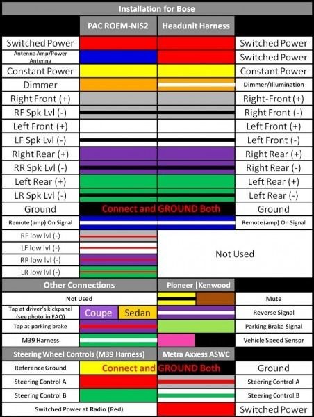
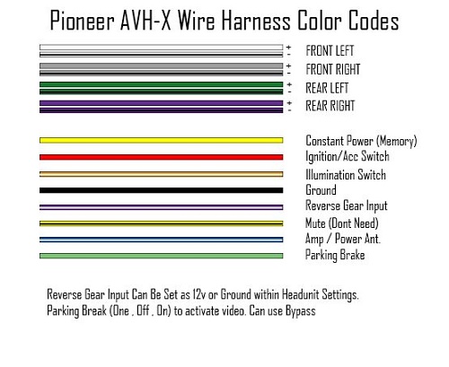
Wire identification and connection. If using a wiring adaptor isn’t an option, you’ll have to carefully consider the function of each wire. Examine each wire individually and connect it to the appropriate wire on the car stereo. The following Pioneer wiring harness color code connections are ideal for this receiver:
- Yellow wire -12 volt cable for terminal supplied with power
- Red wire – serves as a power wire that connects to the car’s red wire
- Black wire – serves as a ground wire that must match the car’s ground wire
- Orange/white – links to lighting terminal
- Connect the power amp using the blue/white cable.
- Violet/white – links to the backlight. This connection informs the driver if the vehicle is traveling forward or backward.
- Light green- attaches to the brake switch to monitor the parking brakes’ status.
- The remaining wires will be used to connect speakers, a subwoofer, a parking camera, rear/front lights, and any other audio components to your receiver. Make sure each wire is connected to the correct automobile cable.
Diagram
All cables must be secured. After you’ve double-checked that all wires are linked to their matching cables, you might want to secure your connections. The goal is to make sure that no bare wires are left exposed. Insulating your wires will help to keep you and those around you safe from electric shock and fire. The simplest method is to connect the wires by wrapping them with electric tape. Another way is to melt a soldering agent onto the wires, which will cause them to adhere together as the solder hardens.
Warnings And Suggestions
Do not install this receiver in any location where the wires may obstruct your eyesight or impair your ability to drive, or where the wiring may interfere with the regular operation of automobile safety equipment such as airbags.
Do not connect the yellow wire to the car’s battery directly. Any vibration that occurs as a result of this could cause short-circuiting, resulting in substantial damage.
Make sure cables aren’t where they’ll be in extreme heat or humidity. The insulation on the leads may wear away if they become hot, resulting in malfunction or irreparable damage. As a result, stay away from heaters, air conditioners, and situations! They might be direct to sunlight or rain.
Cover and wrap any loose cables to keep them from injuring the driver or any passengers if the automobile comes to a sudden halt.
Cut or shorten the cables as little as possible. The leads may not work as expected as a result of this.
Finally, test the wiring to check that it is properly connected before proceeding with the final installation.


