The Kenwood stereo wiring diagram color code from this page will help you to learn all that you need to know about Kenwood radio installation and its wiring diagram. A Kenwood radio might be difficult to set up. The producers urge that you get it installed by a professional.
If you have prior installation expertise, we offer a few pointers that may help you grasp the process.
Kenwood Stereo Wiring Diagram Color Code Overview
Turn off the automobile, remove the key from the ignition, and disconnect the negative connection of the battery. Verify that the input and output wire connections are correct. Reconnect the negative terminal of the battery after installing the unit in the vehicle. Restart the device.
Installation Of The Speaker
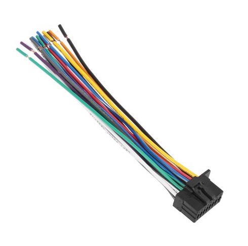
Before you install the unit, make sure the wire bundle is connected. Take note of the speaker wires and their connection places as follows:
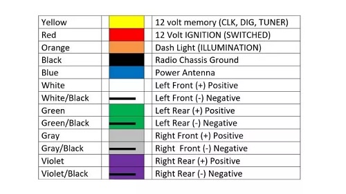
- The white wire on the front left speaker is positive, whereas the black wire is negative.
- The grey wire on the front right speaker is positive, whereas the black wire is negative.
- Then the green wire on the rear left speaker is positive, whereas the black wire is negative.
- The purple cable in the rear right speaker is positive, whereas the black wire is negative.
For remote operation, the steering remote control wires are in connection to the steering. The light blue wire in the steering remote control adapter is positive, whereas the yellow wire is negative. You’ll come across a few more wires! Here is where the connection is in position: The blue wire is not in use in this project. When using the optional power amplifier to the antenna connection in the car, the blue positive and white negative wires connect to the power control terminal. When the phone rings, the brown wires connect to a grounded circuit. You can also check a method to get your lost Kenwood code if you have a locked Kenwood device in your vehicle!
Only three wires should be left. The ignition wire is red, the battery wire is yellow, and the ground wire is black. The red wire is to the fuse box’s ignition power source, the yellow wire to the fuse box’s battery power source, and the black wire to the car’s chassis.
Installation
Before attaching the device, double-check that the escutcheon is pointing in the right direction. Then connect the wiring harness which works is final. Bend the necessary tabs to keep the mounting sleeve in place. Other things to remember when setting up the Kenwood radio:
Only a vehicle with a 12V DC power source with a negative ground is in use to install the Kenwood radio. If the yellow battery wire and the red ignition wire are in link to the car’s chassis, a short circuit may develop. Connect them to the power source that runs via the fuse box at all times.
Disconnect the negative battery wire before installing the gadget. The vinyl tape is in use to cover all disconnected wires. To avoid a short circuit, do not remove any of the caps on the ends of the disconnected wires. After you’ve placed the device, remember to ground it to the car’s chassis once more.
Use only the screws that came with the item.
When opening and shutting your device, make sure the faceplate does not collide with the lid of the console. Once the unit is fully mounted, check all other features such as the brake lights, wipers, blinkers, and other electrical functions. The unit should be installed at no more than a 30° angle.
If the speaker wires are shared or connected incorrectly, the item may not perform properly. It’s never a good idea to mix up the back and front connectors.


